Thermal conductivity of materials, such as laminates, carbon fibers, ceramics, composites, and alloys, is often tested both in-plane and through-thickness to describe the various types of materials. The thermal resistance of interfaces, multi-layer materials, and thin-film materials, as well as the thermal resistance of bonded and attached connections, including IC chips bonded to heat sink material, may all be measured. Testing can be done in a variety of environments, including air, partial atmosphere, vacuum, and inert gas.
BEST STANDARD FOR THERMAL CONDUCTIVITY?
Specific test standards are required in several sectors to certify product characteristics. Different test techniques based on numerous criteria are used for novel application materials that are not yet suitable for certification, product development, and general characterization. Below are detailed explanations of testing capabilities and test methodologies for each system type.
HOT-PLATE SYSTEMS
(ASTM C177, ASTM C1044, ASTM C1114)
ASTM C177 and ASTM C1044 GUARDED-HOT-PLATE SYSTEMS
TK-3 and TK-7 Capabilities:
Guarded-Hot-Plate Systems | Capabilities |
Thermal Conductivity Range | < 0.01 W/(m·K) to 2 W/(m·K) |
Mean Sample Temperature Range | 98 K to 723 K (-175 °C to 450 °C) |
Specimen Size | Identical pair of samples: both 152 mm × 152 mm, ≤25.4 mm thick (6.0″ × 6.0″, ≤1.0″ thick) |
Reproducibility | ±2 % |
Accuracy | ±3 % to ±5 % |
- Thermal conductivity has a practical limit according to ASTM C177. Other test techniques for materials with conductivity >2 W/(mK) produce the best results unless ASTM C177 is necessary.
- The present test system designs limit sample sizes and temperature ranges.
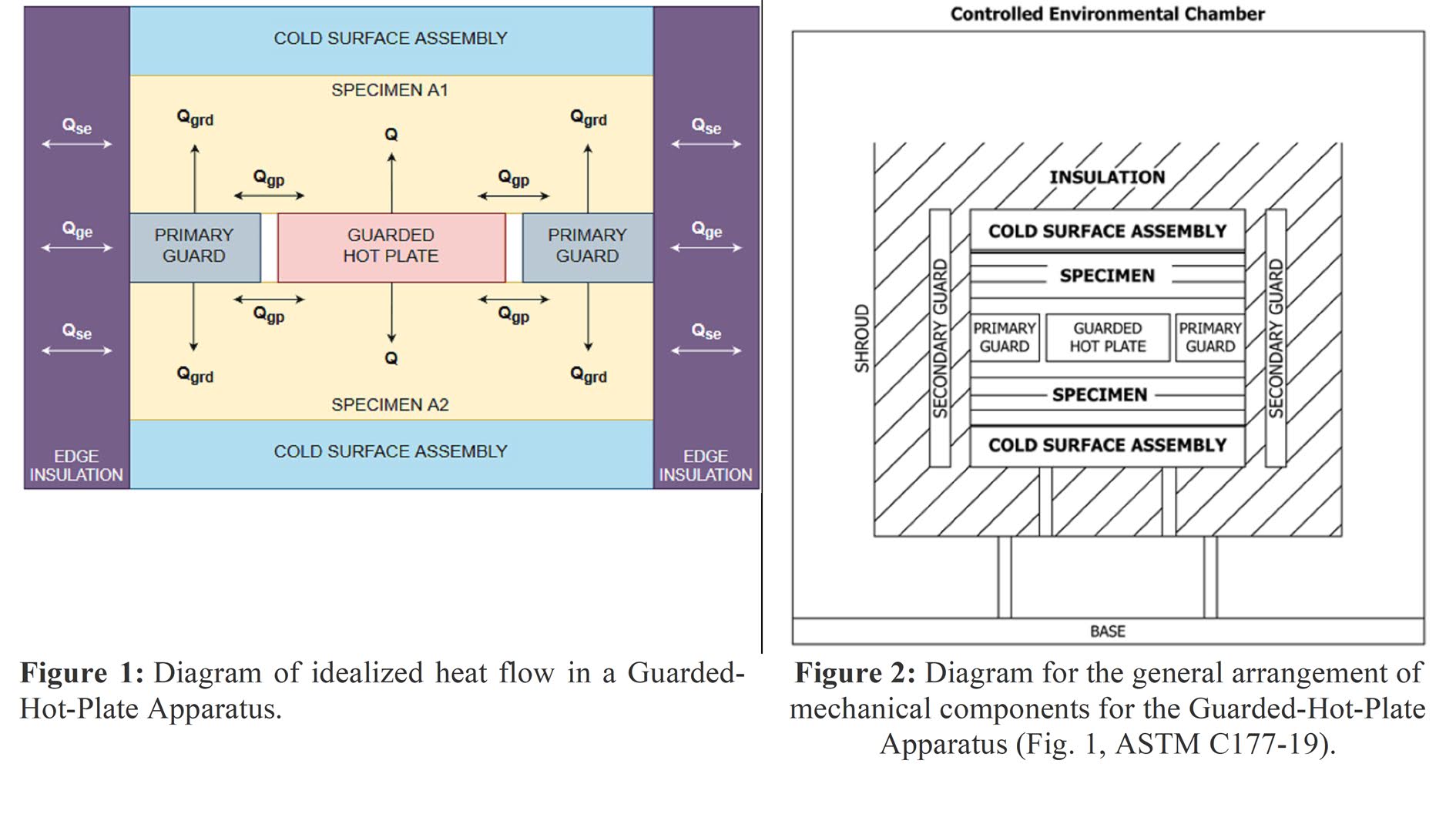
Direct measurement of heat flux through materials is possible with the Guarded-Hot-Plate Apparatus. Specimens are put between the heating and cooling plates in the area between them (Figures 1 and 2). Measurements of the metering area, energy input, temperatures, and specimen thickness are used to compute thermal characteristics. Although ASTM C177 requires two identical specimens, Practice C1044 allows for a single-sided measurement for the same system.
ASTM C1114
With higher temperatures, ASTM C177 has realistic measurement limits. With higher-temperature materials, ASTM C1114 use a thin-heater configuration. Accounting for edge heat loss in specimens is one of the most difficult aspects of ASTM C1114.
HEAT FLOW SYSTEMS (ASTM C518, ASTM E1530, ASTM E1225, ASTM D5470)
ASTM C518, ASTM E1530, ISO 8301 HEAT FLOW METER SYSTEMS
C518 and E1530 system limitations
ASTM C518, ASTM
E1530, ISO 8301 Heat Flow Meter Systems | Capabilities |
Thermal Conductivity Range | 0.01 W/(m·K) to 2 W/(m·K) |
Mean Sample Temperature Range | 98 K to 548 K |
| (-175 °C to 275 °C) |
Standard Specimen Sizes | 25.4 mm squares or 50.8 mm squares, <25.4 mm thick |
| (1″ squares or 2″ squares ≤ 1″ thick) |
Reproducibility | ±2 % |
Accuracy | ±5 % to ±10 % |
- Note 1: Due to flux sensor constraints, the temperature range of the C518 is limited to 233 K to 548 K (-40 °C to 275 °C).
- Note 2: The size of the specimen is restricted by the adaptors’ ability to fit it into existing flux sensor sizes.
- Note 3: The thermal resistances of accessible reference materials and how closely they match the thermal resistance of the specimen determine accuracy.
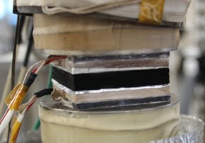
The procedure is deceptively simple: a specimen is placed between two heat flux transducers with uniform thermal contact between a hot plate and a cold plate, as shown in Figure 3. ASTM C518 measurements rely on the calibration of the heat flow meter apparatus and the quality of the heat flux transducers used, but the procedure itself is deceptively simple: a specimen is placed between two heat flux transducers with uniform thermal contact between a hot plate and a cold plate, as shown in Figure 3. Through the test specimen, a steady-state heat flow is established. The temperatures of the plates and the spacing of the plates are recorded.
 |
| Figure 3: In the heat flow meter system, C518 felt sample is placed between heat flux transducers. |
ASTM E1225 and ASTM
D5470 GUARDED-COMPARATIVE-LONGITUDINAL HEAT FLOW SYSTEMS
ASTM E1225 and D5470 Systems
ASTM E1225, ASTM
D5470 Guarded-Comparative-Longitudinal Heat Flow Systems | Capabilities |
Thermal
Conductivity Range | 0.2 W/(m·K) to 400 W/(m·K) |
Mean Sample
Temperature Range | Currently tested from 45 K to 873 K |
| (-228 °C to 600 °C) |
Standard Specimen
Sizes | Solids, liquids, pastes |
Reproducibility | ±2 % |
Accuracy | ±5 % to ±10 % |
- Note 1: For conventional E1225 and D5470 testing, a specimen size of 25.4 mm square or Ø 25.4 mm adaptors is required.
- Note 2: Accuracy is affected by the conductivity of the specimen and the substance.
The specimen is placed between two reference materials (meter bars) with a homogeneous compressive force to produce the testing stack. A temperature gradient is produced by maintaining a temperature differential between two actively heated and cooled plates. To calculate the steady state temperature gradient, a minimum of two temperature sensors are installed in each stack element. The apparent heat flow in the meter bars is computed per unit area. The temperature-dependent thermal conductivity of the specimen is subsequently computed.
ASTM D5470 and ASTM E1530 THIN MATERIALS and COATINGS STACKING TESTS
 |
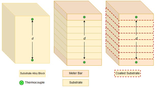
| Figure 4: Three specimen stacks of increasing layers and thicknesses are examined to quantify the thermal conductivity of materials that are too thin to measure reliably at thickness. Specimens that fit 25.4 mm square adapters are generally desirable but not necessary. |
The apparent thermal conductivity of a thin material may be estimated using the observed thermal resistance and specimen thickness. When compared to the thermal resistance of the specimen, the interfacial thermal resistance must be insignificantly minimal (no more than 1%).
By eliminating the interfacial thermal resistance, the apparent thermal conductivity of a sample material may be precisely measured. This is achieved by measuring the thermal resistance of the material at three different thicknesses d and graphing the thermal resistance vs thickness (Figure 4). The apparent thermal conductivity is the inverse of the slope of the resultant straight line. The contact resistances at the two surfaces are added to provide the intercept at zero thickness. This stacking approach may also be used to calculate coating thermal conductivity. Alloy substrates are coated and tested with the customer’s material. As illustrated in Figure 5, the results are then computed against bare alloy blocks and bare alloy stacks.
 |
| Figure 5: The measurement of thermal conductivity of coatings is depicted graphically. When testing in accordance with ASTM E1530, flux sensors are utilized in place of meter bars. |
THERMAL INTERFACE MATERIAL (TIM) TESTING:
Thermal pads, greases, adhesives, gap fillers, tapes, phase transition materials, and metal thermal interface materials may all have their thermal conductivity tested at room temperature. Multiple bond line thicknesses (BLTs), unique aging histories, and curing circumstances are often desired to be evaluated for optimum data of their materials in use.
Texpedi.com
Check out these related articles:
